Basic Sciences

QUESTIONS
Before continuing, try to answer the following questions. The answers can be found at the end of the article, together with an explanation.
- Regarding anisotropy, which of the following statements is correct?
- Anisotropy never impacts on image quality.
- Anisotropy is less pronounced when the structure being examined has many curved surfaces.
- Changing the angle of the probe by 5–10° can result in some structures not being seen at all.
- The sciatic nerve is the largest peripheral nerve in the human body and when being imaged using ultrasound, anisotropy is of little consequence.
- The concept of anisotropy is of academic value, but has little bearing on the practicalities of using medical ultrasound.
- Concerning the Doppler effect and ultrasound, which of the following statements is correct?
- Doppler ultrasound is used to examine immobile structures.
- The Doppler shift refers to the increasing use of Doppler ultrasound in clinical practice.
- Red blood cells moving toward an ultrasound transducer produce a decrease in the frequency of the reflected sound.
- A positive Doppler shift occurs when blood flow is toward the ultrasound transducer.
- The optimal doppler shift can be detected when the angle of incidence between the probe and the blood flow is 90°.
- Regarding linear array ultrasound probes, which of the following statements are correct?
- They are low frequency probes.
- They have poor axial resolution.
- They are best for visualizing superficial structures.
- They produce a sector shaped field.
- They penetrate tissues deeply.
INTRODUCTION
In part 1 of this article (ATOTW 199 – The physics of ultrasound – part 1) we looked at the basic physical principles of sound waves and how they govern the generation, application and limitations of medical ultrasound. Part 2 will examine more closely some ultrasound phenomena, such as anisotropy and artefact, that in practice can greatly affect the image quality obtained. Through understanding these it will be possible anticipate when they may occur, how they will impact on the image quality and what practical steps can be taken to mitigate their effects.
Following this we will look at the Doppler effect and its implications for medical ultrasound before finishing with a few practical hints and tips on how to ensure the best images are obtained.
Anisotropy
The amount of beam reflected back to the transducer can be dramatically reduced by small changes in the angle that the transducer is held in relation to the organ being examined. This is known as anisotropy. This is accentuated when there are many curved surfaces or when the organ is made up of numerous layers that are not parallel. This gives a distorted image with heterogeneity in appearance when in reality all the tissue is the same. With smaller structures such as tendons and nerves, it can make the difference between the structure being seen or not. For this reason, understanding anisotropy is extremely important when performing peripheral nerve blocks under ultrasound guidance. If we take the example of the sciatic nerve, the largest nerve in the human body, this can often be difficult to visualize clearly despite its size. This is due to two factors: 1. the relatively deep position of the nerve, with thick overlying muscle layers that attenuate the ultrasound beam and 2. the morphology of the nerve itself, which promotes anisotropy. To minimise the impact of anisotropy, it is essential to maintain the probe and beam perpendicular (at 90°) to the nerve (see Figure 1). As the angle is varied from 90°, the visibility decreases and changes of only 5–10° can result in the nerve not being seen at all (see Figure 2).
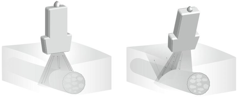
Figure 1: Illustration demonstrating anisotropy (see text for description)
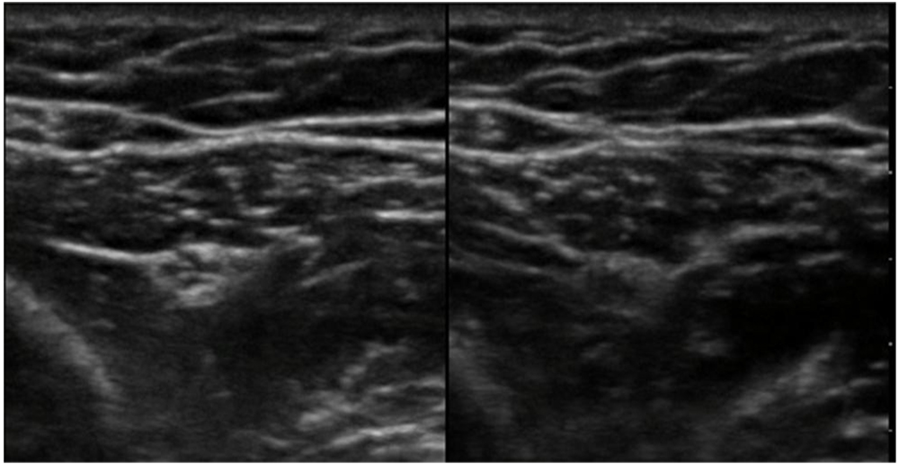
Figure 2: Scan showing anisotropy in practice. The area scanned is the same; the probe angle is different.
Artefact
An artefact is an image, or part of an image, that does not correspond to the anatomy of the region being examined. Artefacts can be useful in the interpretation of an image, or more commonly can obscure information. Examples of artefact include acoustic enhancement, acoustic shadowing and reverberation.
Acoustic enhancement or post-cystic enhancement occurs when sound energy passes through a fluid-filled structure such as the urinary bladder, cysts or blood vessels. More sound energy passes through the fluid as very little is reflected and therefore the tissues behind the fluid appear bright. Hence the fluid acts as an ―acoustic window‖ for deeper structures. This is vey useful in, for example, pelvic scans where a full bladder acts as an acoustic window to visualize deeper tissues. It may however make it difficult to clearly identify nerves that lie behind vessels for example the radial nerve which lies deep to the axillary artery when performing an ultrasound-guided axillary block.
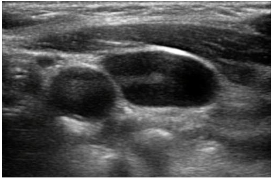
Figure 3: Here the tissue behind the carotid artery and internal jugular vein can be seen to appear brighter than the surrounding tissues because of this effect.
Acoustic shadowing, on the other hand, is the opposite of acoustic enhancement and occurs when sound energy hits a highly reflective structure such as bone cortex, calculi or a nerve block needle leaving little ultrasound energy to reach deeper structures. The tissues immediately behind these dense structures appear dark. This can be useful when scanning the gallbladder as gallstones can be recognised by their posterior ―comet-tail shadow.‖ However, shadowing is mostly problematic. For instance, ribs in the upper abdomen and chest can obscure deeper structures (see Figure 4).
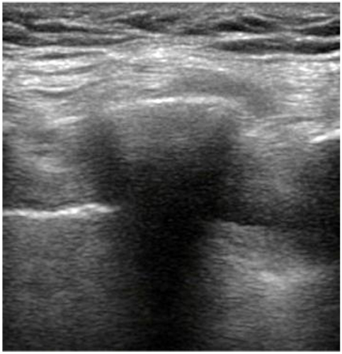
Figure 4: A rib is shown here obscuring lung and pleura behind it.
Reverberation is caused by multiple sound wave reflections between a structure and ultrasound probe or between two structures and appears as parallel, evenly-spaced lines. The sound wave ―bounces‖ and returns to the probe a few times, producing an image with each reflection and can occur if too little gel is used. This can also be seen when performing an in-plane ultrasound-guided nerve block (see Figure 5).
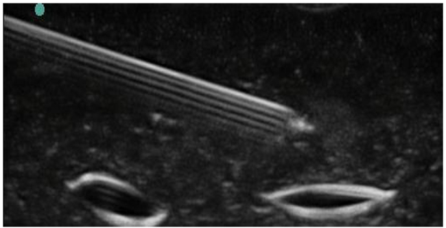
Figure 5: Scan showing reverberation artefact occurring from an in-plane needle.
DOPPLER EFFECT
The Doppler effect is a phenomenon first described by Austrian physicist Christian Doppler in 1842. It is the change in frequency for an observer moving relative to the source of the wave. A common example given to illustrate this effect is when a vehicle sounding a siren approaches, passes, and moves away from a stationary observer. During the approach, the sound waves are compressed and of shorter wavelength and therefore the frequency is higher (than the emitted frequency). At the point of passing the wavelength and frequency are identical to those being emitted. As the vehicle recedes the wavelength increases and the frequency falls. This change in frequency is called the doppler effect and to the observer is perceived as a change in pitch (see Figure 6).
Emitted waves are reflected off an object that is moving toward the transducer, then the frequency at which they return will be increased. Likewise, if the object is moving away from the transducer then the frequency will be decreased. By measuring the change in frequency, the direction and speed of movement can be calculated. This has a number of applications but most commonly doppler ultrasound is used in the assessment of blood flow.
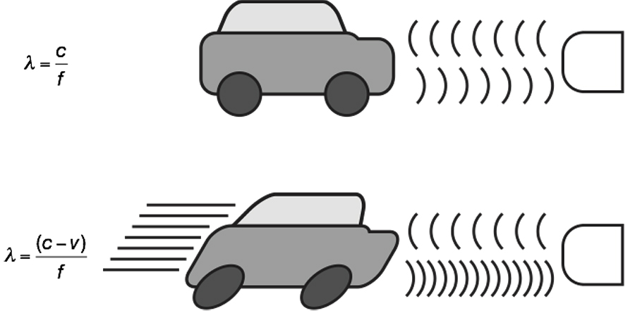
Figure 6: Illustration to show how frequency of waves change with changing position.
How does doppler ultrasound measure blood flow?
In diagnostic ultrasound, the reflectors of the sound waves are the red blood cells. Directing an ultrasound beam at moving red blood cells allows the transducer to detect two separate frequencies:
- The transmitting frequency of the transducer (ft)
- The received frequency (reflected from the cells) (fr)
The motion of the red blood cells will determine whether or not there is a discernible change between ft and fr. In practice, one of the following three situations will occur:
- The red blood cells are stationary relative to the transducer and therefore ft= fr
This is represents zero Doppler shift. - The red blood cells are moving toward the transducer and therefore fr > ft
This is a positive Doppler shift. - The red blood cells are moving away from the transducer and therefore ft > fr
This is a negative Doppler shift.
The Doppler shift refers to the difference between the transmitted and received frequencies that in the case of blood flow, occurs due to the motion of the red blood cells relative to the transducer. The size of the shift is directly proportional to the velocity of the moving column of blood, and the polarity of the shift indicates the direction of flow (positive shift=blood moving toward the transducer; negative shift=blood moving away from the transducer).
The Doppler equation
The size of the Doppler shift is dependent on:
- The frequency of the sound transmitted from the transducer
- The velocity of the column of blood
- The angle between the direction of blood flow and the ultrasound beam
The Doppler equation describes the relationship between these three.

Where:
- fD= Doppler shift
- f0= transmitted frequency
- v= velocity of blood flow
- c= speed of sound in tissue
- α= angle between the ultrasound beam and the blood flow
As the transmitted frequency, speed of sound in tissue and Doppler shift is known, this equation can be re-arranged to calculate the velocity of the blood flow (v).
Cosine of 90°=0. This means that the ultrasound beam is perpendicular to the blood flow, there will be no Doppler shift, and the velocity cannot be calculated. An incident angle of between 30° and 60° with the vessel lumen gives the best angle to estimate the velocity.
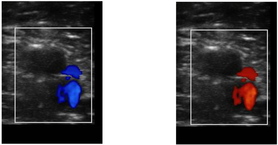
Figure 7: Doppler ultrasound of a vessel. The different colouring is applied by the machine to indicate that when the probe has been angled flow is detected either towards (red) or away (blue) from the receiver.
PRACTICAL APPLICATION OF THE PHYSICAL PRINCIPLES
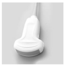
Different types of probe
Three types probe are used for the vast majority of 2D ultrasound imaging:
1. Linear arrays—high frequency (6–13 MHz). These provide the greatest axial resolution, but the higher the frequency the more attenuation occurs as they pass through the tissues, limiting the depth of penetration. As a general rule, the highest frequency probe available for the depth of target to be imaged should be used. Linear arrays are typically used to produce finely-sampled images with a rectangular field of view. They are best for superficial structures (e.g. brachial plexus).

2. Curved arrays—low frequency (2–5 MHz). These are able to image deeper structures, but with a decreased axial resolution. They produce a diverging ̳sector-shaped‘ field of view that expands beyond the lateral extent of the transducer. They are best for large or deep structures (e.g. sciatic nerve).
3. Phased arrays—these probes consist of many small ultrasonic elements that can be pulsed individually. By varying the timing a tightly-focused, high resolution beam can be produced that may be electronically steered. This beam can then be swept, like a searchlight, through the tissue being examined. The data from multiple beams is put together to form a visual image with the expanding field of view that is characteristic of curved arrays. These probes are predominantly used for echocardiography.
In addition, the physical size of the probe may limit its application, for example in paediatric patients. In these cases, smaller probes may be used.
Practical aspects of obtaining an optimal image
In addition to selecting the correct machine, probe and settings, here are some practical tips that will help ensure you obtain the best images possible.
- Place the probe lightly on the skin over the target tissue, ensuring an air-free contact using gel or alcohol spray
- Small changes in pressure, angulation, rotation or tilt of the transducer probe can dramatically improve or worsen your image. Change only one aspect at a time.
- The transducer should be held in the hand that allows optimum scanning and needle position. For the best ergonomics, the ultrasound machine should be positioned on the contra lateral side of the patient and the operator should operate from the ipsilateral side of the extremity to be blocked.
- Orientate the probe to mirror your hand movements by ensuring that when your hand moves the probe to the left, the image on the screen moves to the left and vice versa.
- Identify the appropriate landmarks such as blood vessels to orientate yourself. Nerves can often be easier to identify if they situated near a vessel and their relationship to the vessel is known, e.g. femoral nerve lies lateral to the femoral artery and vein.
- Move the probe over the region of interest, visualizing your target and noting its relationship to other anatomical structures
- Gentle application of pressure may help you distinguish between arteries and veins. As will using colour Doppler.
- Keep your target in the middle of your field of view.
SUMMARY
- Positioning the probe at 90° to the structure that you wish to image is essential for the best acuity and also to prevent losing smaller important structures such as nerves on the ultrasound screen.
- A good knowledge of the regional anatomy being visualised and an awareness of different forms of artefact, can help distinguish pathology from artefact.
- Red blood cells reflect ultrasound and this is the basis for measuring blood flow with Doppler ultrasound.
- Use an ultrasound system with a high frequency transducer (up to 13MHz) for superficial blocks that are less than 3cm deep. This allows for the best resolution of the neural structures and surrounding tissue. Deeper blocks will require a lower frequency transducer that provides better penetration of the ultrasound beam into the tissue.
- Operator ergonomics is vastly improved by careful attention to patient positioning and the preparation of all the equipment prior to the procedure.
ANSWERS TO QUESTIONS
- Regarding anisotropy, which of the following statements is correct?
- FALSE—It often impacts image quality.
- FALSE—It is accentuated by such structures.
- TRUE
- FALSE—The structure and anatomical position of the sciatic nerve give a very anisotropic nature.
- FALSE
- Concerning the Doppler effect and ultrasound, which of the following statements is correct?
- FALSE—It is most commonly used to assess mobile media such as blood flow.
- FALSE—The Doppler shift refers to the change in frequency seen in the Doppler effect.
- FALSE—They produce an increase.
- TRUE
- FALSE—At an angle of 90° there will be no Doppler shift.
- Regarding the linear array ultrasound probe:
- FALSE—They are low frequency probes.
- FALSE—They have good axial resolution.
- TRUE— They are best for visualizing superficial structures.
- FALSE—They produce a rectangular shaped field.
- FALSE—They do not penetrate tissues deeply.
FURTHER READING
- http://totw.anaesthesiologists.org/2010/10/04/the-physics-of-ultrasound-part-1-199/
This work by WFSA is licensed under a Creative Commons Attribution-NonCommercial-NoDerivitives 4.0 International License. To view this license, visit https://creativecommons.org/licenses/by-nc-nd/4.0/