Intensive Care Medicine

Part 2 of a 3 part series focuses on common abnormalities found in the ICU.
MULTIPLE CHOICE QUESTIONS
- Features of consolidation on chest x-ray include:
- Tracheal shift towards the consolidated side
- Air bronchograms
- Effusion around the consolidated area
- Loss of the right heart border in right middle lobe consolidation
- Left lower lobe collapse:
- Can be subtle on the frontal film
- Can cause the “sail sign”
- Can cause the “Golden S-sign”
- The lobe collapses anteriorly and laterally
- Pleural effusion:
- Gives rise to a meniscus in the supine position
- Lung markings may be visible through the effusion
- Can be due to pulmonary embolus if unilateral
- Can be due to hypothyroidism
- Pneumomediastinum:
- Always indicates oesophageal rupture
- Air may be visible around vessels
- A pneumothorax must also be present
- Is commonly seen in ARDS patients
COMMON ABNORMALITIES
This section summarises CXR findings for various conditions. Patients do not tend to arrive with a diagnosis plastered to their forehead so this may seem the wrong way around to go about learning CXR skills. However, radiological findings should follow your own history and examination findings. In the ICU, the patient has often been examined by others and had previous CXRs too. Thus, arriving at a diagnosis is often a process of working both “forwards” by piecing together clinical and radiological findings and also by judiciously working “backwards” looking for specific findings associated with a differential diagnosis under consideration. On the whole, more forwards and less backwards leads to more accurate diagnoses!
This section is split into two halves. Firstly, core CXR findings are discussed. These are not exclusive to ICU patients but appear commonly on CXRs taken in ICU. Secondly, CXR findings which are particular to ICU are discussed.
CORE CXR FINDINGS
Lungs
Radio-opaque areas have characteristic appearances, which typically represent one of three processes: consolidation, collapse, effusion or some combination of these (e.g. consolidation with a reactive pleural effusion). You should note the position of the trachea to help separate these three.
Consolidation
Consolidation denotes fluid filling of the space within the alveoli and is therefore also known as alveolar or air-space shadowing. The fluid may be exudate, transudate, blood, protein and infiltration – either malignant or non-malignant. The exact type of fluid is impossible to discern from the X-ray alone, so the clinician will need to consider the patient’s history and other investigations to narrow the differential further. Causes include:
- Exudate: due to infection (bacterial, viral, fungal, protozoal)
- Transudate: either cardiogenic or non-cardiogenic (e.g. ARDS)
- Blood: due to trauma, infarcts or pulmonary vasculitis (e.g. Goodpasture’s)
- Protein: alveolar proteinosis
- Infiltration
- Malignant: Alveolar cell carcinoma, lymphoma, metastases
- Non-malignant: sarcoid, amyloid
Since consolidation is simply replacement of air space by fluid, the mobile structures of the thorax (the trachea, mediastinum, lung fissures and hemidiaphragm for example) will not be displaced from their normal positions. A cardinal feature of consolidation is the air bronchogram – infiltration of oedema around the bronchi leaving a dark tubular structure (the air-filled bronchiole) surrounded by radio-opaque fluid.
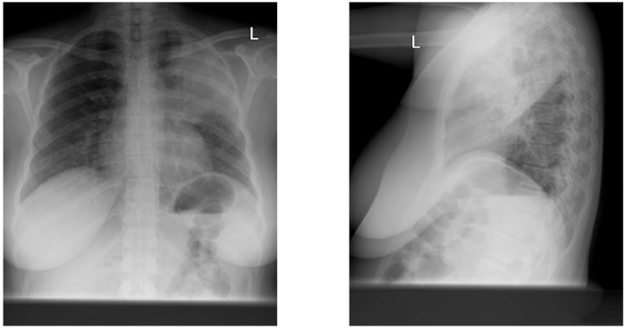
Figure 1. Left upper lobe consolidation. Air bronchograms are clearly visible in the left upper zone on the PA film. The lateral film shows that the area is defined posteriorly by the left oblique fissure, localising it to the upper lobe.
Collapse
Volume loss results in increased opacification which may look similar to consolidation or effusion. The primary sign is displacement of a fissure.
Secondary signs are:
- Elevation of hemidiaphragm
- Crowding of ribs
- Increased density of collapsed lobe
- Compensatory expansion of non-collapsed lobe
- Displacement of hila
- Mediastinal shift
The key sign in differentiating this from consolidation is that movement of the fissure does not occur with pure consolidation of a lobe, although clearly mixed processes are possible.
The cause of the collapse may be evident from the chest X-ray too. Bronchi may be blocked “from the inside” by a tumour (consider bronchogenic, carcinoid and metastases), a foreign body or a mucus plug, or from “from the outside” by a mass, a large pleural effusion or a pneumothorax.
The following examples show the patterns seen in collapse of the various lobes
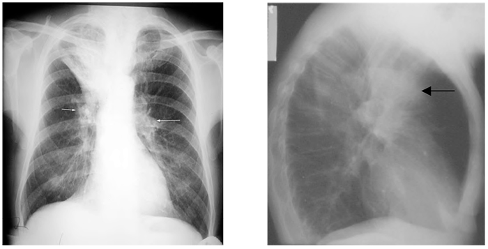
Figure 2. Right upper lobe collapse. The right hilum, normally lower than the left, has moved up (arrows) and the right transverse fissure has moved upwards, indicating volume loss. Right upper lobe collapse is less visible on the lateral film as the upper zone is often partly obscured by the overlying shoulders and upper arms. This example (from a different patient) demonstrates the triangular opacity of the upper lobe giving a “V”-like shadow in the upper zone. An “S-shaped” appearance can be caused (not in this example of a right sided hilar mass responsible for the collapse, merging with the outline of the collapse itself) -the Golden sign.????
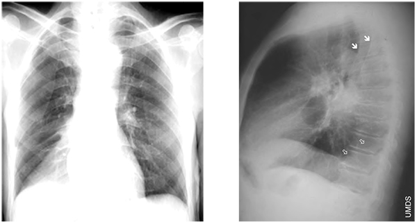
Figure 3. Right lower lobe collapse. Triangular opacity in the right lower zone. The clear right heart border and obscured hemidiaphragm localise this to the lower lobe (silhouette sign) and the downward movement of the oblique fissure demonstrates collapse. The solid arrows are the borders of the scapulae and the open arrows outline the displaced oblique fissure.
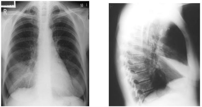
Figure 4. Right middle lobe collapse. Ill- defined shadowing is evident adjacent to the right heart border, which becomes indistinct. This is often not immediately obvious on the frontal film, but when suspected, is a good indication for a lateral film. The collapsed lobe is clearly seen on the lateral film as a thin wedge between the horizontal and oblique fissures, which are displaced.
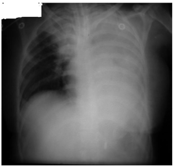
Figure 5. Left lung and right upper lobar collapse as a consequence of endobronchial intubation. Note the upward bowing of the right transverse fissure, distinguishing this from consolidation. The position of the trachea remains fairly central, as the bilateral collapse balances movement of the mediastinum.Figure 5. Left lung and right upper lobar collapse as a consequence of endobronchial intubation. Note the upward bowing of the right transverse fissure, distinguishing this from consolidation. The position of the trachea remains fairly central, as the bilateral collapse balances movement of the mediastinum.
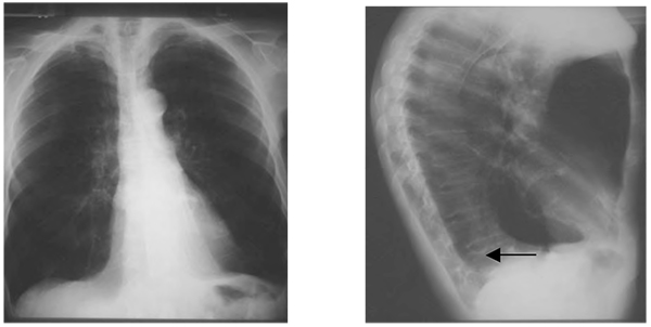
Figure 6. Left lower lobe collapse. The left lower lobe collapses medially and posteriorly to lie behind the heart. It classically displays a triangular opacity which may be visible through the cardiac shadow, or may overlie it, giving the heart an unusually straight lateral border, the so-called “sail sign”. The hemidiaphragm may be obscured where the opacity lies against it. The findings on the lateral film are subtle, but increased density over the lower thoracic spine with a sharp margin is indicated by the arrow.
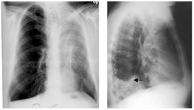
Figure 7. Left upper lobe collapse. The left upper lobe collapses forwards and downwards, giving an extensive “veil-like” opacity over the left lung field. The extent of the left upper lobe can be appreciated from the fact that it occupies a large area of the lung field in the PA view. The lower lobe expands behind the collapse. The lateral film in this example also contains a pleural effusion (arrow).
Effusion
Fluid in the inter-pleural space may cause a radio-opaque appearance as well. In contrast to a collapsed lung, volume gain causes the mobile structures of the lung to move away from the side of the effusion. The fluid will settle under gravity leaving a fluid level at the top. If the patient is upright this fluid level, a “meniscus”, may be visible. Theoretically, if the patient is perfectly supine the fluid will spread evenly across the lung obscuring both the hemidiaphragm and the apex, leaving the pulmonary vessels still visible.
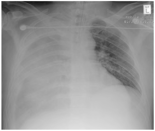
Figure 8. Supine patient with a right pleural effusion. The apex and hemidiaphragm are obscured and pulmonary vascular markings are subtly visible. The trachea is central, suggesting that although the right lung appears entirely affected, the effusion is not sufficient to create a mass effect.
Clinicians should be aware of the causes of a pleural effusion and should look for signs of these, guided by the history and examination findings. Causes of a pleural effusion may be split into unilateral (such as tumour, infective, embolus) or bilateral (heart failure, nephrotic syndrome, cirrhosis, protein-losing enteropathy and hypothyroidism ∗)
Other findings within the lung include:
Linear structures within the lungs
There are several different types, whose appearances can be difficult to separate out.
- Septal lines: 1-2mm thick, 1-2cm long. These represent areas of interstitial fluid or tissue such as interstitial pulmonary oedema, lymphangitis carcinomatosa or interstitial lung disease
- Subsegmental collapse
- Lace-like pattern: “reticular” usually longstanding, caused by fibrosing alveolitis, scleroderma or drugs
- Honeycomb appearance: often seen in chronic endstage disease
- Rings with tram lines: suggest bronchiectasis
- Rings without tram lines: suggest cystic lung disease
- Rings that are very thin resembling round cysts: pneumatocoeles
- Tubular lines: represent vessels (serpigenous – AV malformations) or bronchi filled with pus (glove fingers)
Nodules
The delineation between micronodules, nodules and masses is purely arbitrary. Here, nodules are taken as up to 3cm in diameter.
<1mm: micronodules as seen with alveolar microlithiasis
1-3mm: miliary nodules. These can result from sarcoid, metastases, pneumoconiosis, or alveolitis due to drugs or extrinsic allergens.
3mm-3cm: metastases or abscesses
Masses
These are focal nodular lesions bigger than 3cm. The causes are limited:
- Neoplasm: primary bronchogenic or metastatic
- Abscess
- Haematoma: usually in trauma
- Vasculitis: usually in the presence of a known underlying condition such as rheumatoid arthritis or Wegener’s granulomatosis
Pneumothorax
Although many abnormalities are characterised by increased opacification in the lung, clinicians should be aware that some abnormalities are characterised by decreased opacification (“radio-lucency”). It is embarrassing to correctly identify a difference in opacification between the two lungs only to describe a suspected abnormality in the wrong lung. A pneumothorax – defined as gas in the inter-pleural space – is characterised by a visible pleural edge as the visceral pleura contracts towards the hilum with an absence of vessel markings beyond it. The area “beyond” the visceral pleura will be radiolucent since it contains air.
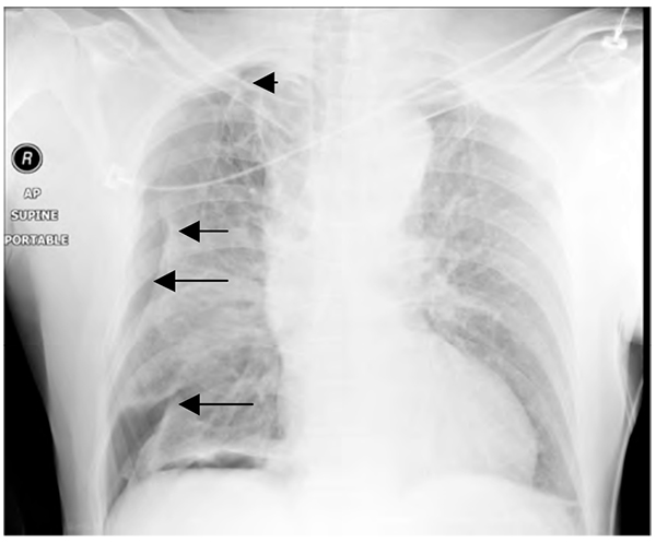
Figure 9. (Traumatic) pneumothorax. The edges of the collapsed lung are shown by the arrows.
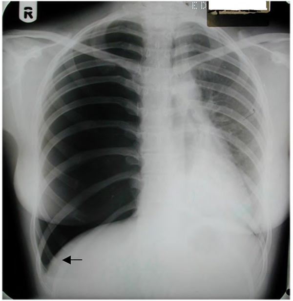
Figure 10. Right-sided tension pneumothorax. Absence of right-sided lung markings, the “deep sulcus sign” (arrow) and significant mediastinal shift are visible on the “x-ray that should never be seen”.
Pneumomediastinum and subcutaneous emphysema
For air to enter the mediastinum the alveoli, trachea or oesophagus must rupture. Trauma or barotrauma are often underlying causes.
Findings on the chest X-ray include streaks and bubbles in the mediastinum, air outlining the mediastinal vessels, the mediastinal pleura or the superior aspect of the diaphragm.
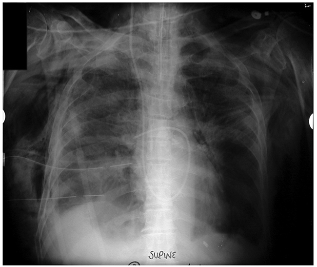
Figure 14. Barotrauma with drained right pneumothorax, massive subcutaneous and mediastinal air, pulmonary artery flotation catheter, nasogastric and endotracheal tubes. A not untypical Xray before the advent of lung-protective ventilation for ARDS.
Traumatic aortic injury
Patients that are well enough to have a CXR demonstrating an aortic injury are a selecting group – they are not dead. In itself this suggests that haemorrhage has tamponaded, leading to a mediastinal haematoma. Radiological features of a traumatic aortic injury can therefore be split into those that represent the effect (a mediastinal haematoma) and those that represent a cause.
Mediastinal haematoma
- Mediastinal widening >8cm at the level of the aortic arch
- Mediastinal to chest ratio of >33%
- Deviation of the nasogastric tube and trachea to the right
- Depression of the left main bronchus
- Left apical pleural shadowing or “cap”
- Loss of clarity or lobulated arch of the aorta
Cause
- Rib fractures
- Scapular, vertebral or sternal fractures
- Left hemothorax or effusion
- Left pneumothorax
- Lung contusion
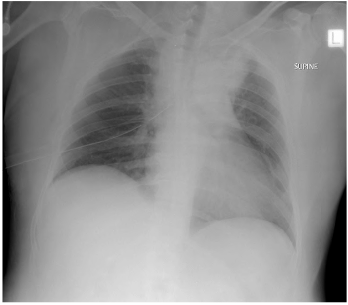
Figure 15. Drained right pneumothorax and widened mediastinum, suggestive of traumatic great vessel injury.
ANSWERS TO QUESTIONS
- Features of consolidation:
- False. The hallmark of consolidation is that it does not cause mediastinal, hilar or movement of fissures.
- True
- True
- True
- Left lower lobe collapse:
- True
- True
- False. This is a feature of right upper lobe collapse due to obstructing carcinoma.
- False. Medially and posteriorly
- Pleural effusion:
- False. This is a characteristic of effusions in the erect position
- True
- True
- True
- Pneumomediastinum:
- False
- True
- False
- True but far less common in recent years, due to low tidal volume ventilation.
REFERENCES:
- Figures 2, 3, 4, 6 and 7 along with some of the accompanying text, are reproduced from the website of the Scottish Radiology society, SRS-X, www.radiology.co.uk/srs-x, with thanks to Dr. Andrew Downie.
ACKNOWLEDGEMENT
Many thanks to Bruce McCormick for his advice on the manuscript, and to Bruce McCormick and Andrew Lockwood for the use of their collections of CXRs.
BIBLIOGRAPHY
- Howling S, Jenkins P. Radiology for MRCP. Cheshire, UK: PasTest; 1998.
- Raby N, Berman L, de Lacey G. Accident & Emergency Radiology. 2nd ed. London: Elsevier; 2005.
- Chan O. ABC of Emergency Radiology. 2nd ed. Oxford, UK: Blackwell; 1995.
- Patel PR. Lecture Notes on Radiology. Oxford, UK: Blackwell; 1998.
This work by WFSA is licensed under a Creative Commons Attribution-NonCommercial-NoDerivitives 4.0 International License. To view this license, visit https://creativecommons.org/licenses/by-nc-nd/4.0/